You are using an out of date browser. It may not display this or other websites correctly.
You should upgrade or use an alternative browser.
You should upgrade or use an alternative browser.
Building one of the world's most absurd commercial chassis hearses (a turbo build thread)
- Thread starter Psychoholic
- Start date

- Joined
- May 28, 2018
- Messages
- 163
- Reaction score
- 62
- Points
- 28
- Location
- Loganville, GA
- What vehicle(s) do you drive?
- 72 Miller Meteor
If you like wholesale destruction and the process of taking a wooded lot and getting ready for our mondo slab pour then this video is the one you want to watch!
Apparently going from forest to having a finished slab in 5 weeks is positively unheard of but here we are. Enjoy!
Apparently going from forest to having a finished slab in 5 weeks is positively unheard of but here we are. Enjoy!
- Joined
- May 28, 2018
- Messages
- 163
- Reaction score
- 62
- Points
- 28
- Location
- Loganville, GA
- What vehicle(s) do you drive?
- 72 Miller Meteor
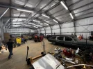
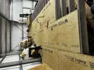
I know it's been a while but I figured I'd pop in real quick for an update on what we've been working on (instead of my Caddy). We have finally finished my damned building! It is a 50'x100' on a 120' wide pad (wanted the side pad to park cars). It's a whopping 18' tall at the eves and has a 750 sq/ft mezzanine for storage. Still a bunch of wiring to be done (we got the lights and back wall done last weekend) but we are ready to start moving in! Still have to finish the mezzanine and build a bathroom but we can do all that later.
It's hard to get a sense of scale of the building so just use the person doors to judge the size since those are standard size doors. In the last pic you can see my friend who is about 5'9". The roll up doors are 12' wide and 14' tall at the openings.


It's hard to get a sense of scale of the building so just use the person doors to judge the size since those are standard size doors. In the last pic you can see my friend who is about 5'9". The roll up doors are 12' wide and 14' tall at the openings.
- Joined
- May 28, 2018
- Messages
- 163
- Reaction score
- 62
- Points
- 28
- Location
- Loganville, GA
- What vehicle(s) do you drive?
- 72 Miller Meteor
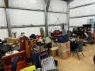
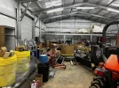
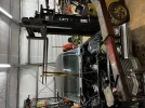
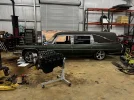
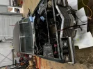
Well we are fully moved in as of yesterday! New shop is an unmitigated disaster of chaos but we were just grabbing and going as fast as we could so nothing is where it goes. I can tell that the stress of the building being finished has left me since now I can't sleep because I'm lying awake at night dreaming of working on my car/motorcycles/gokart. As soon as we get the lifts up my beloved Morticia will be going into her own bay so we can get back to work (to quote Letterkenny 'pitter patter, bud').
Attachments
- Joined
- May 28, 2018
- Messages
- 163
- Reaction score
- 62
- Points
- 28
- Location
- Loganville, GA
- What vehicle(s) do you drive?
- 72 Miller Meteor
Nicolas
Member
- Joined
- Mar 9, 2022
- Messages
- 32
- Reaction score
- 4
- Points
- 8
- What vehicle(s) do you drive?
- calillac
@Psychoholic Great work, keep us posted with your progress! ")
- Joined
- May 28, 2018
- Messages
- 163
- Reaction score
- 62
- Points
- 28
- Location
- Loganville, GA
- What vehicle(s) do you drive?
- 72 Miller Meteor
Obviously not Cadillac related but we finished the floor of the mezzanine yesterday! It's so freaking sturdy and nice (the rating is 50 psf static load). Now we can start putting stuff away so we can get the machines making money again and install the lifts so I can get back to working on my freaking car.

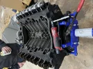
I've also gone down a deep and dark rabbit hole I'm afraid I won't recover from regarding the electronics in my car. I was working on a flowbench design for us to test the porting of heads and came up with some rather ridiculous ideas using can-bus instead of just wiring things directly. Sure - why the hell wouldn't you have an MQTT message broker installed in a car and send all of your sensor data that doesn't have sub 500 ms response needs to it? Also realized I haven't posted any pics of my engine in forever so here is one I took the other day with the intake just sitting on the motor.

I've also gone down a deep and dark rabbit hole I'm afraid I won't recover from regarding the electronics in my car. I was working on a flowbench design for us to test the porting of heads and came up with some rather ridiculous ideas using can-bus instead of just wiring things directly. Sure - why the hell wouldn't you have an MQTT message broker installed in a car and send all of your sensor data that doesn't have sub 500 ms response needs to it? Also realized I haven't posted any pics of my engine in forever so here is one I took the other day with the intake just sitting on the motor.
Attachments
CrashTestDummy
Member
- Joined
- Mar 5, 2012
- Messages
- 126
- Reaction score
- 4
- Points
- 18
Nice shop! As usual, too small!!Well we are fully moved in as of yesterday! New shop is an unmitigated disaster of chaos but we were just grabbing and going as fast as we could so nothing is where it goes. I can tell that the stress of the building being finished has left me since now I can't sleep because I'm lying awake at night dreaming of working on my car/motorcycles/gokart. As soon as we get the lifts up my beloved Morticia will be going into her own bay so we can get back to work (to quote Letterkenny 'pitter patter, bud').
") Ours is only 4800 sq. ft., but what it lacks in size, it makes up for in just being a nice, dry place to go work on projects in.
Ours is only 4800 sq. ft., but what it lacks in size, it makes up for in just being a nice, dry place to go work on projects in. Loving the FI hearse!!
- Joined
- May 28, 2018
- Messages
- 163
- Reaction score
- 62
- Points
- 28
- Location
- Loganville, GA
- What vehicle(s) do you drive?
- 72 Miller Meteor
Hey guys! I'm still alive, I promise!
Much has changed in the life of our hero. I got notice at the end of August that I was getting laid off in September, got a new job, worked there for a while, got laid off AGAIN and have spent the last month looking for a new job. Happy to report that I start on Monday and I'm PUMPED.
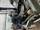
Given that I had a week between all the paperwork getting done and starting I actually was able to take some time to work on my car. Most weekends I would have had time to work on my car have been spent knocking out customer orders to offset the cost of the shop.
It's funny how something so simple as putting a freaking dipstick tube in can spiral into 'screw it, we're pulling the motor'. I also figured that I need to redo the seals in the steering box and couldn't get to them with the headers still on the motor and in the car so it made sense. This is what we are deeming 'version 1' where we're just working towards getting the fuel injection system working. I've been doing some pretty hard geeking on the side playing with CAN bus stuff for my moron strength dashboard and data logging. Pretty sure I'm going to have the most technologically advanced '72 Cadillac on the face of the earth by the time she fires off for the first time.
I have a 12.3" touch screen I'm going to be replacing the gauge cluster with which necessitated a way to drive it. So I'm doing a Raspi4+. I want to be able to report things like fuel level to the gas gauge digitally and instead of using an Arduino (the ADC setup on a Raspi are laughable) I've got a bunch of can modules to report back to the Pi. I grabbed a brand new 2014 CTS-V steering wheel and I wanted to be able to use the buttons on it which are using voltage division instead of switches so I bought a can interface from ECUMasters that will do all the logic for me and report that to the ECU and dash. I don't want to do a mechanical speedo anymore either so adding a GPS module plus a bunch of wheel speed and driveshaft speed sensors so I can detect wheel slip, adjust the steering input levels on the eventual electric assist rack by way of speed etc.
Much has changed in the life of our hero. I got notice at the end of August that I was getting laid off in September, got a new job, worked there for a while, got laid off AGAIN and have spent the last month looking for a new job. Happy to report that I start on Monday and I'm PUMPED.
Given that I had a week between all the paperwork getting done and starting I actually was able to take some time to work on my car. Most weekends I would have had time to work on my car have been spent knocking out customer orders to offset the cost of the shop.
It's funny how something so simple as putting a freaking dipstick tube in can spiral into 'screw it, we're pulling the motor'. I also figured that I need to redo the seals in the steering box and couldn't get to them with the headers still on the motor and in the car so it made sense. This is what we are deeming 'version 1' where we're just working towards getting the fuel injection system working. I've been doing some pretty hard geeking on the side playing with CAN bus stuff for my moron strength dashboard and data logging. Pretty sure I'm going to have the most technologically advanced '72 Cadillac on the face of the earth by the time she fires off for the first time.
I have a 12.3" touch screen I'm going to be replacing the gauge cluster with which necessitated a way to drive it. So I'm doing a Raspi4+. I want to be able to report things like fuel level to the gas gauge digitally and instead of using an Arduino (the ADC setup on a Raspi are laughable) I've got a bunch of can modules to report back to the Pi. I grabbed a brand new 2014 CTS-V steering wheel and I wanted to be able to use the buttons on it which are using voltage division instead of switches so I bought a can interface from ECUMasters that will do all the logic for me and report that to the ECU and dash. I don't want to do a mechanical speedo anymore either so adding a GPS module plus a bunch of wheel speed and driveshaft speed sensors so I can detect wheel slip, adjust the steering input levels on the eventual electric assist rack by way of speed etc.
Attachments
- Joined
- May 28, 2018
- Messages
- 163
- Reaction score
- 62
- Points
- 28
- Location
- Loganville, GA
- What vehicle(s) do you drive?
- 72 Miller Meteor
At some point I need to draw a line in the sand (and not on a Etch-a-sketch) and deem 'ok, this is enough' and quit adding new projects to this project.
Unrelated: I bought a '60 Sedan Deville that used to belong to a friend who passed rather suddenly. My friends are trying to talk me into keeping it but I don't want to take away time or funds from my hearse build.
I have most of the ECU wiring on my bench at the house right now. I have added an ECUMaster PMU-16 and a 12 button CAN keypad to the mix. If you have not played with one of these PMUs it is an absolute game changer of the highest order. The car will be almost completely devoid of fuses and relays now and the logic you can use with it is super rad. Because of this addition I had to rethink the overall wiring strategy for the car which means even more wiring. It has 10 x 25A channels and 6 x 15A channels that you control completely through CAN so I'm moving all of the following to it:
Wellllll since that would only leave the alternator and the power steering pump attached to the front of the motor I then decided it was time to go after the power steering and I'm doing an electric pump out of a Mini Cooper (since that thing is like 80A by itself I am doing a 100A breaker and a 100A relay that I can trigger off of a high side out on the ECU). Nice thing about that is that if the car is off I can tell the computer to turn on power steering and moving it around will be a dream even with the car not running.
I am running a lower pulley off of a 3.0 Taurus and then just the 400A alternator.
When I talk about logic puzzles here is one for you: Lets say you have the headlights on (which means the parking lights are running), you have your foot on the brake, and you turn on the left turn signal. So that means you have to light up the front/rear left turn signals while also lighting up the right brake light but not the left so it will actually blink. Fun abound.
Fortunately I'm making good progress on the bench and I took a few classes on HPAcademy.com on CAN communications, wiring, and PDM configuration so that helped out A TON. If you haven't done a class there it is totally worth every single penny. I did find a coupon code through their podcast of 'podcast75' and it gets you $75 off if you are interested.
Unrelated: I bought a '60 Sedan Deville that used to belong to a friend who passed rather suddenly. My friends are trying to talk me into keeping it but I don't want to take away time or funds from my hearse build.
I have most of the ECU wiring on my bench at the house right now. I have added an ECUMaster PMU-16 and a 12 button CAN keypad to the mix. If you have not played with one of these PMUs it is an absolute game changer of the highest order. The car will be almost completely devoid of fuses and relays now and the logic you can use with it is super rad. Because of this addition I had to rethink the overall wiring strategy for the car which means even more wiring. It has 10 x 25A channels and 6 x 15A channels that you control completely through CAN so I'm moving all of the following to it:
- Fans
- Starter solenoid
- Headlights low
- Headlights bright
- Wipers fast
- Wipers slow
- Turn signals left
- Turn signals right
- Fuel pump
- Water pump
- Brake lights
- Parking lights
- ECU/dashboard
- Car fuse block for interior lights
Wellllll since that would only leave the alternator and the power steering pump attached to the front of the motor I then decided it was time to go after the power steering and I'm doing an electric pump out of a Mini Cooper (since that thing is like 80A by itself I am doing a 100A breaker and a 100A relay that I can trigger off of a high side out on the ECU). Nice thing about that is that if the car is off I can tell the computer to turn on power steering and moving it around will be a dream even with the car not running.
I am running a lower pulley off of a 3.0 Taurus and then just the 400A alternator.
When I talk about logic puzzles here is one for you: Lets say you have the headlights on (which means the parking lights are running), you have your foot on the brake, and you turn on the left turn signal. So that means you have to light up the front/rear left turn signals while also lighting up the right brake light but not the left so it will actually blink. Fun abound.
Fortunately I'm making good progress on the bench and I took a few classes on HPAcademy.com on CAN communications, wiring, and PDM configuration so that helped out A TON. If you haven't done a class there it is totally worth every single penny. I did find a coupon code through their podcast of 'podcast75' and it gets you $75 off if you are interested.
- Joined
- May 28, 2018
- Messages
- 163
- Reaction score
- 62
- Points
- 28
- Location
- Loganville, GA
- What vehicle(s) do you drive?
- 72 Miller Meteor
My name is Chris and I have a problem...
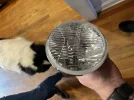
Electric water pump and adapters are here. Also am swapping out all the lights with LEDs which meant I needed to do headlights too. Opted for a set of the Holley RetroBright in modern white and they are massively fancy and beautiful.
The issue I'm going to have with the Mini Cooper power steering pump is that the damned thing pulls north of 80A (once again, quite glad I have a 400A alternator) so I needed to feed it from something other than the PMU. Using a marine grade 100A circuit breaker wired straight to the battery (well a distribution lug anyway) and a big ass solid state relay that I'm triggering from a high side output on the ECU.
My weird logic puzzle did find it's way into working finally. I was WAY over complicating things. Since I'm not doing the interior lights off of the PMU I still need constant power from a fuse block I was able to move some stuff around and free up some channels on the PMU. So now I'm also running 'left brake' and 'right brake' on their own channels so I can turn off the brake light on the side that is blinking. Still need to figure out how to show that the brakes are on if the hazards are on.
Seriously though if you haven't considered a PMU I HIGHLY HIGHLY recommend it. This is the way to do it here forward even on a hotrod.

 photos.app.goo.gl
Electric water pump and adapters are here. Also am swapping out all the lights with LEDs which meant I needed to do headlights too. Opted for a set of the Holley RetroBright in modern white and they are massively fancy and beautiful.
The issue I'm going to have with the Mini Cooper power steering pump is that the damned thing pulls north of 80A (once again, quite glad I have a 400A alternator) so I needed to feed it from something other than the PMU. Using a marine grade 100A circuit breaker wired straight to the battery (well a distribution lug anyway) and a big ass solid state relay that I'm triggering from a high side output on the ECU.
My weird logic puzzle did find it's way into working finally. I was WAY over complicating things. Since I'm not doing the interior lights off of the PMU I still need constant power from a fuse block I was able to move some stuff around and free up some channels on the PMU. So now I'm also running 'left brake' and 'right brake' on their own channels so I can turn off the brake light on the side that is blinking. Still need to figure out how to show that the brakes are on if the hazards are on.
Seriously though if you haven't considered a PMU I HIGHLY HIGHLY recommend it. This is the way to do it here forward even on a hotrod.
New video by Chris DiGanci
photos.app.goo.gl
Attachments
- Joined
- May 28, 2018
- Messages
- 163
- Reaction score
- 62
- Points
- 28
- Location
- Loganville, GA
- What vehicle(s) do you drive?
- 72 Miller Meteor
So this is what a timing chain should look like (this is the new Cloyes one I just put in and spent an hour degreeing)
 photos.app.goo.gl
Aaaaaaand this is what the $35 chain looks like after less than 15k miles looked like:
 photos.app.goo.gl
I have also designed and made what might be the world's first 'modern steering wheel to antique column clock spring':

Since I am doing a fancy wheel from a 2016 CTS-V and I want the buttons to work I needed a way to get the CANH/CANL + 12v + ground wires down the column. I searched FOR MONTHS for something that would work and ended up getting a spring from a Freightliner then stealing the cable from it and making an all new mechanism. That is printed in PETG with carbon-fiber in it so it's strong as shit and heat resistant.
New video by Chris DiGanci
photos.app.goo.gl
Aaaaaaand this is what the $35 chain looks like after less than 15k miles looked like:
New video by Chris DiGanci
photos.app.goo.gl
I have also designed and made what might be the world's first 'modern steering wheel to antique column clock spring':
Since I am doing a fancy wheel from a 2016 CTS-V and I want the buttons to work I needed a way to get the CANH/CANL + 12v + ground wires down the column. I searched FOR MONTHS for something that would work and ended up getting a spring from a Freightliner then stealing the cable from it and making an all new mechanism. That is printed in PETG with carbon-fiber in it so it's strong as shit and heat resistant.
- Joined
- May 28, 2018
- Messages
- 163
- Reaction score
- 62
- Points
- 28
- Location
- Loganville, GA
- What vehicle(s) do you drive?
- 72 Miller Meteor
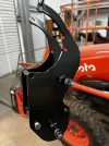
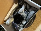
Got a little distracted (only mildly - I'm not actually touching this one until my car is back on the road) and did something a little dumb.
- Joined
- May 28, 2018
- Messages
- 163
- Reaction score
- 62
- Points
- 28
- Location
- Loganville, GA
- What vehicle(s) do you drive?
- 72 Miller Meteor
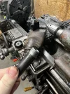
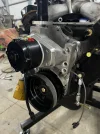
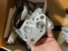
Been making some good progress on the motor. The electric water pump input is straight in the way for where the alternator belt so opted to move it down to the bottom right if looking from the front. Obviously nobody makes a kit for this so we got a little creative and honestly I'm a little proud of our solution. I took the fuel pump block off plate and duplicated it in 1/8" steel on our plasma and made a bracket for the heim joint to fit, connected it to the back of the alternator (which puts it almost in the middle of the housing which is nice for even pressure) and just made another bracket off the water pump to locate the top bolt. You could just about stand on that alternator and it wouldn't budge. The pulley is off of a Taurus and we had to machine the opening up about .05" to make it fit (it's tiiiiiiiiiight) and open up the top hole a little bit for the locating pattern. Once we were done with all that we powder coated everything in Columbia Coatings Satin Black.


Also welded some 1/4-20 bolts to the top of the valve cover to mount the coils. Bought some coil brackets from Summit that keep everything nice and tidy. The plug wires should look really clean doing it this way and the loom for each bank of coils should also look fairly nice. Only a few more things to do while the motor is out like Cerakote the headers but we're REAL close to stabbing it back in.


Also welded some 1/4-20 bolts to the top of the valve cover to mount the coils. Bought some coil brackets from Summit that keep everything nice and tidy. The plug wires should look really clean doing it this way and the loom for each bank of coils should also look fairly nice. Only a few more things to do while the motor is out like Cerakote the headers but we're REAL close to stabbing it back in.
- Joined
- May 28, 2018
- Messages
- 163
- Reaction score
- 62
- Points
- 28
- Location
- Loganville, GA
- What vehicle(s) do you drive?
- 72 Miller Meteor
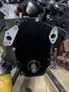
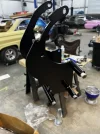
I know it's been a while since I posted some progress pics but made some hellaciously good progress yesterday and now the motor is finally ready to go back in!
I made a decision a few months ago that I was going this far down the rabbit hole so I might as well do air conditioning. Bought a really dope kit from RestomodAir (The Vapiir II) which meant I needed a compressor which meant a re-imagining of my pulley setup again. This took a LOT of brainin and figurin but I'm super pumped about it came out. I used the same tensioner I made in the previous post but the rest was done again from scratch. Cut the main brackets out of 3/8" steel on my plasma, used some 3/4" round bar stock with a 3/8" hole for bolt pass through, made some stand offs for the pulleys to align them. To describe this setup as 'sturdy' wouldn't be giving the word enough credit. I'd be extremely confident picking up the motor from that bracket it is so strong.
Also powder coated the front timing cover and the water pump housing because I can.